

What Is a Solenoid Valve and How Does It Work?
A Solenoid Valve is a compact electromechanical device that controls liquid or gas flow. It uses an energized coil, a magnetic field, and a movable plunger. When voltage reaches the coil, the plunger shifts and opens or closes an internal passage. Remove the power, and a spring usually returns it. The action can happen in milliseconds. You can hear a sharp click near a pneumatic actuator or see a water line stop instantly.
Industry demand reflects this practical value. Grand View Research estimated the global Solenoid Valve market at approximately US$4.6 billion in 2022. Its report also projected steady growth through 2030, supported by factory automation, medical equipment, and water systems. MarketsandMarkets offered a higher estimate, forecasting growth from about US$5.1 billion in 2023 to US$7.1 billion by 2028. These figures differ. That difference deserves attention, because market definitions and product categories are not always consistent.
Hydraulic systems educator Brendan Casey has emphasized, “A component is only as reliable as the system around it.” That warning applies directly here. A correctly sized valve can still fail when voltage is unstable, fluid is contaminated, or the coil overheats. This guide explains how a Solenoid Valve works, how normally closed and normally open designs differ, and where selection mistakes commonly occur. The explanation is practical, but not perfect. Real installations contain noise, heat, pressure spikes, and maintenance gaps. Understanding those details turns a simple click into dependable control.
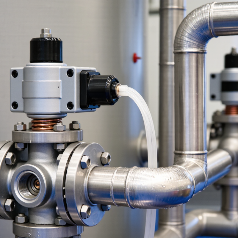
Solenoid Valve Fundamentals: 2/2-Way, 3/2-Way, and Normally Open Designs
What Is a Solenoid Valve and How Does It Work?
A solenoid valve uses electricity to control fluid or gas flow. Its coil creates a magnetic field when energized. This field moves a metal plunger, opening or closing an internal passage. When power stops, a spring usually returns the plunger. The valve then follows its normal, or resting, position.
A 2/2-way valve has two ports and two positions. It commonly turns flow on or off in a single line. A 3/2-way valve has three ports and two positions. It can supply pressure to one outlet while venting another. This design suits pneumatic cylinders and directional control. Normally closed valves block flow without power. Normally open valves allow flow without power and close after energizing. Choosing between them depends on safety, process behavior, and what should happen during power loss. A neat diagram can mislead. Real systems need pressure, temperature, seal, and response-time checks.
Tips: Confirm the port markings before installation. Check the fluid’s compatibility with the seal material. Keep voltage within the coil rating. I have seen wiring errors create symptoms that look like mechanical faults. Also, do not assume every 3/2-way valve works with every actuator. The exhaust path matters, especially when movement must be quick. A small pressure difference can change performance. That detail is easy to overlook.
What Is a Solenoid Valve and How Does It Work? - Solenoid Valve Fundamentals: 2/2-Way, 3/2-Way, and Normally Open Designs
| Design or Parameter | Definition / Construction | Operation When the Coil Is De-energized | Operation When the Coil Is Energized | Typical Uses and Selection Notes |
|---|---|---|---|---|
| Solenoid valve | An electrically actuated valve that uses a magnetic field from a coil to move a plunger, diaphragm, or piston and control fluid flow. | The return spring or differential pressure places the valve in its defined fail position. | The magnetic field moves the internal actuator to open, close, or redirect the flow path. | Used for rapid on/off control of air, water, gases, oils, steam, and other compatible media. |
| 2/2-way normally closed (NC) | Two ports and two positions: one inlet and one outlet, with the flow path closed in the normal state. | Flow is blocked between the inlet and outlet. | The flow path opens, allowing fluid to pass from the inlet to the outlet. | Common for filling, dosing, water control, compressed air, and safety shutoff applications where flow should stop after power loss. |
| 2/2-way normally open (NO) | Two ports and two positions, with the flow path open in the normal state. | Fluid can pass from the inlet to the outlet without electrical power. | The valve closes and stops the flow while the coil remains energized. | Useful when continuous flow is preferred during a power interruption or when energizing the coil should create a shutoff action. |
| 3/2-way normally closed | Three ports and two positions: typically supply, outlet, and exhaust ports for controlling a single-acting actuator. | The outlet is commonly connected to exhaust while the supply is blocked, depending on the valve configuration. | The supply is connected to the outlet, pressurizing the downstream actuator or circuit. | Often used to operate single-acting pneumatic cylinders, grippers, and spring-return actuators. |
| 3/2-way normally open | Three ports and two positions, arranged so the outlet has a flow connection in the normal, de-energized state. | The outlet is commonly connected to the supply, while the exhaust path is closed. | The supply is blocked and the outlet is commonly connected to exhaust, releasing downstream pressure. | Selected when an actuator should remain pressurized or active without power, subject to the required safety function. |
| Direct-acting construction | The solenoid plunger directly opens or closes the main orifice. | The spring normally holds the plunger against the valve seat or in the specified fail position. | The plunger moves directly under magnetic force to change the flow path. | Can operate with zero differential pressure; often used for smaller flow rates and compact systems. |
| Pilot-operated construction | The solenoid controls a pilot orifice, while system pressure moves a diaphragm or piston across the main valve opening. | The diaphragm or piston remains in its spring- and pressure-controlled position. | The pilot passage changes pressure above or below the diaphragm or piston, opening or closing the main path. | Suitable for higher flow capacities, but it generally requires a minimum pressure differential to function correctly. |
| Normal state | The valve condition with the coil de-energized and the actuator at rest. | Defines whether the valve is normally open, normally closed, or connected to an exhaust path. | The energized state may be the opposite of the normal state, depending on the design. | Always verify the required fail-safe condition before choosing NC or NO operation. |
| Flow direction | The permitted direction of fluid movement through the valve, usually marked by an arrow or port designation. | Flow is restricted or routed according to the de-energized position. | Flow is permitted or redirected according to the energized position. | Installing the valve against its specified flow direction can cause malfunction, leakage, or excessive pressure loss. |
| Response time | The time required for the valve to move between defined positions after an electrical command. | The return time depends on spring force, pressure conditions, viscosity, and internal friction. | The opening or closing time depends on coil power, valve construction, media, temperature, and pressure. | Use the manufacturer’s tested response-time specification when synchronizing fast pneumatic or fluid-control sequences. |
| Key selection criteria | Electrical, mechanical, fluid, and environmental requirements used to match a valve to an application. | The fail position must suit the safety and process requirements during loss of power. | The coil voltage and duty rating must match the control system. | Check port size, flow coefficient, pressure range, temperature range, media compatibility, seal material, enclosure rating, and duty cycle. |
Note: “Normally” refers to the valve’s de-energized state. Actual port connections, pressure limits, flow capacity, and response times vary by valve design and application.